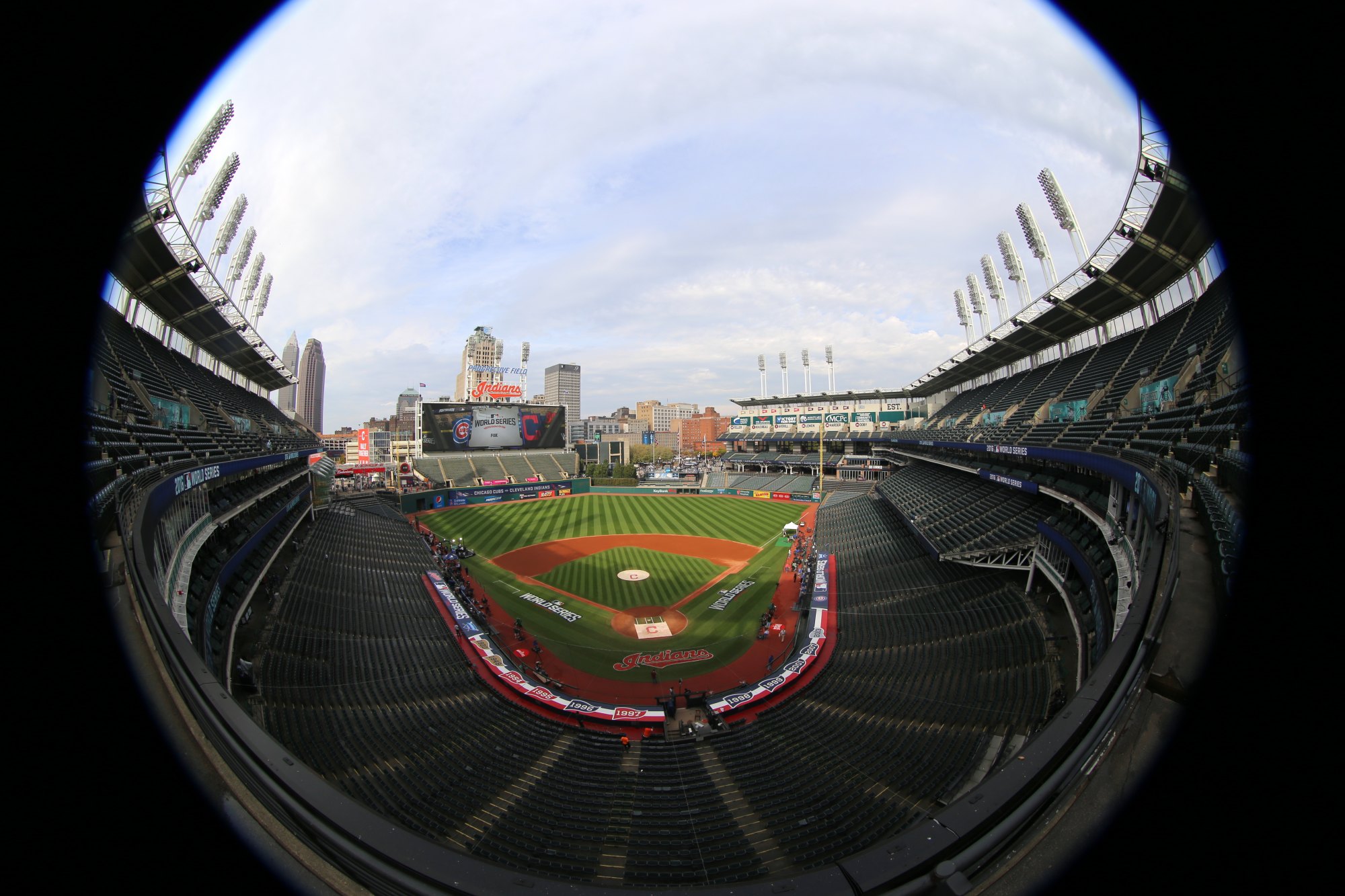
Photo: Arturo Pardavila III, CC BY 2.0, Wikimedia Commons Computer Vision, lecture 2
Image formation
How a camera turns light into a grid of numbers
Last lecture ended with "a picture is a grid of numbers". Today we ask: where do these numbers come from?
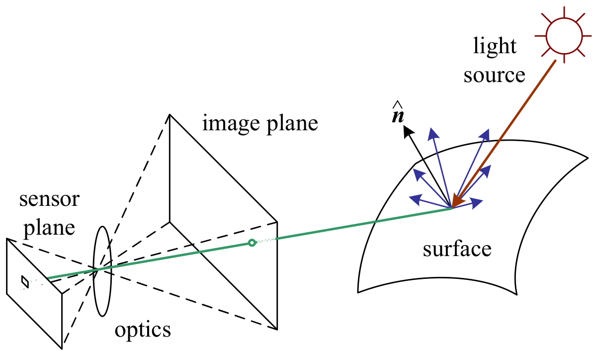
We follow one ray of light: from a lamp, to an object, through a lens, onto the camera's sensor, through some electronics, and into a file.
Why this matters: every method later in the course makes assumptions about how pictures are made. If you understand how a picture is made, you know what we can and cannot get back from it. This is the "graphics in reverse" idea from lecture 1.
The title photo was taken with a fisheye lens. Notice how straight lines bend. We will see why today.
Last time's question
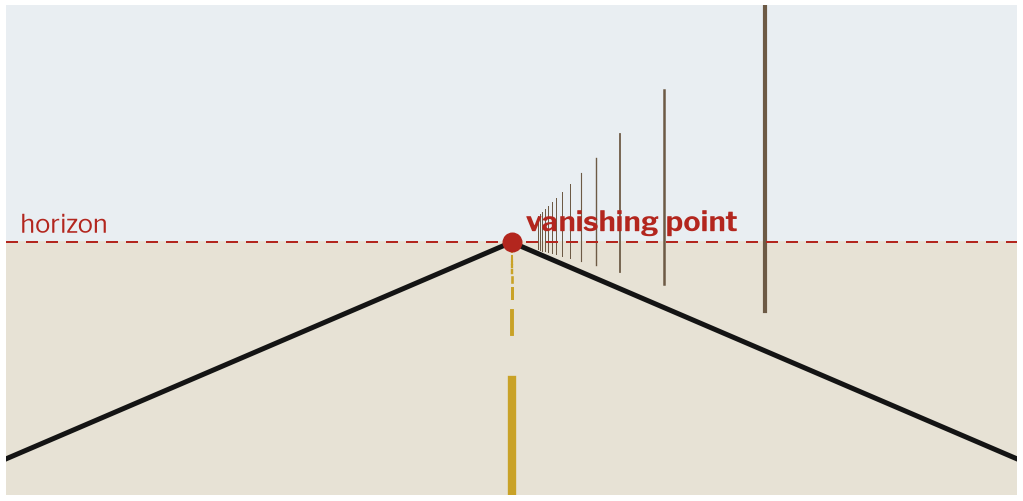
Why do the two sides of a straight road meet at one point?
This is the question from the end of lecture 1. Collect two or three answers before you explain.
Common answers: "because it's far away", "perspective", "that's how eyes work". All are partly right, but none explains it. Tell students: in 15 minutes you will be able to calculate where that point is.
Also point at the poles. In the real world they are the same distance apart. In the picture they get closer and closer. So a picture does not keep distances. It also does not keep angles: the road sides are parallel, but in the picture they make a V shape.
The path of a ray of light
Szeliski (2022), Fig. 2.14
Geometry : where does a point land in the picture?Lenses : how does a lens collect light?Light and colour : how bright and what colour ?Numbers : how does the camera turn light into numbers?
This is the plan for today. Write the four words on the side of the board. Tick each one when you finish it.
The split is useful, not only for teaching. Where a point lands depends on the camera's position and lens. How bright it is depends on the light and the material. These two are mostly separate. Later methods use this: 3D methods use only geometry, and colour methods use only light.
Part 1: Geometry
Where does a point in the world land in the picture?
This part has the most maths today. But it is all about similar triangles, which students know from school.
The pinhole camera
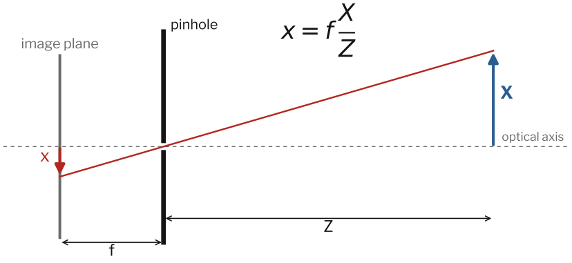
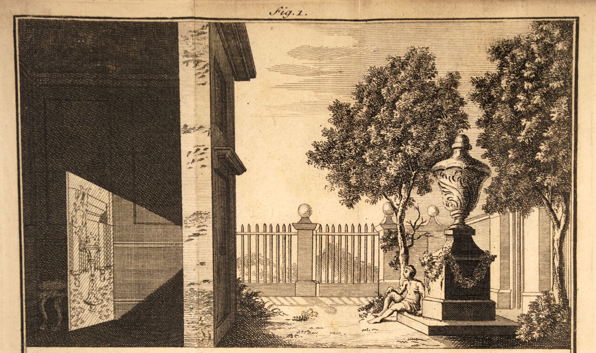
Camera obscura, 1755. James Ayscough, public domain, via Wikimedia Commons Two similar triangles: f x = Z X x = f Z X y = f Z Y
Draw this on the board yourself, step by step. It is the most important drawing today.
Draw a wall with a tiny hole. Behind it, draw a screen at distance f
Draw an object (an arrow) with height X Z
Draw one straight line from the top of the arrow, through the hole, to the screen.
Show the two triangles: a big one outside (sides X Z x f
Say these results out loud:
We divide by Z Twice as far away means half as big in the picture. This is perspective.The picture is upside down , because the light line crosses through the hole. Cameras and our brain turn it back. In maths we often put the screen in front of the hole to avoid the minus sign.
f focal length . A bigger f
The engraving on the right is a camera obscura ("dark room" in Latin): a dark room with a small hole in one wall. The garden outside appears upside down on the opposite wall. People have used this for hundreds of years. You can make one with a shoebox, or with a dark room and a small hole in the curtain.
Why parallel lines meet
A point on a line going in direction d P ( t ) = P 0 + t d
x ( t ) = f Z 0 + t d Z X 0 + t d X t → ∞ f d Z d X
The end point depends only on the direction d P 0
So all lines with the same direction meet at one point: the vanishing point .
Lines parallel to the picture (d Z = 0
This answers the road question with three lines of maths. Go slowly.
Imagine walking along the road. t
When t P 0
The left and right sides of the road start at different places, but they have the same direction. So they go to the same point in the picture.
For a road straight ahead, the direction is ( 0 , 0 , 1 ) x = 0
Check: "Where is the vanishing point of the vertical poles?" Their direction is ( 0 , 1 , 0 ) d Z = 0
Other camera models
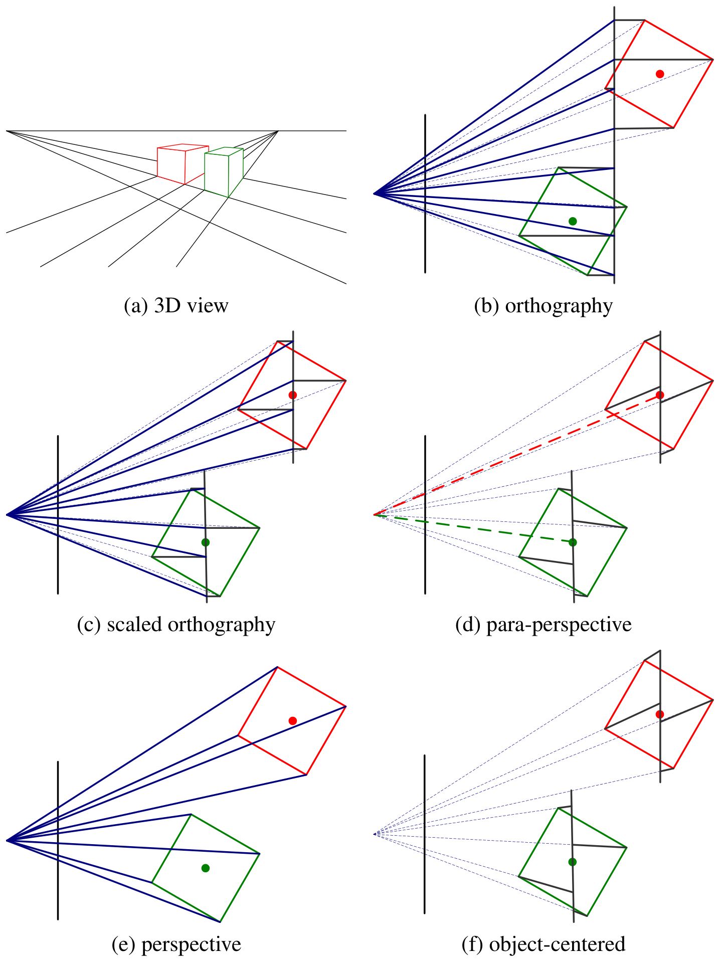
Szeliski (2022), Fig. 2.7 Orthographic : x = X , y = Y
Students only need two models:
Perspective : the pinhole we just learned. We divide by distance.Orthographic : we ignore distance completely.
When is orthographic good enough? When everything is "about equally far away". Examples: a city photographed from a satellite, a face photographed from 100 m with a long lens, cells under a microscope. Then dividing by Z
Ask: "Is a selfie closer to orthographic or to perspective?" Very perspective. The nose is about 10% closer to the camera than the ears, so it looks about 10% bigger. That is why noses look big in selfies, and why portrait photographers stand further back and zoom in.
From metres to pixels: the matrix K
A picture uses pixels, and pixel (0, 0) is at the top left:
u = f x Z X + c x v = f y Z Y + c y
With homogeneous coordinates this is one matrix multiplication:
λ u v 1 = K (intrinsics) f x 0 0 0 f y 0 c x c y 1 X Y Z Two changes from the pinhole formula:
Units. f f f x = f / ( width of one pixel ) f x ≈ 2900 Starting point. Pixel numbers start at the top-left corner. But the centre of the lens points at the middle of the sensor, at pixel ( c x , c y ) principal point . So we add c x c y
Homogeneous coordinates , in simple words: we add a 1 at the end of the point. We agree that ( a , b , c ) ( 2 a , 2 b , 2 c ) Z Z one matrix multiplication . We will use this again in lecture 8.
K intrinsic matrix ("intrinsic" means "belonging to the thing itself"). It belongs to the camera and lens, not to where the camera stands.
Where the camera is: R and t
A world point first moves into the camera's view, then it is projected:
λ u v 1 = K [ R ∣ t ] X w Y w Z w 1
R t extrinsics , 6 numbersK intrinsics , 4 numbers (f x , f y , c x , c y P = K [ R ∣ t ] camera matrix
Keep this simple: two steps. First, move the world so that the camera is at the centre and looks forward. Then, project. Do not explain rotation matrices in detail here.
A simple comparison: [ R ∣ t ] where you stand and where you look . K which lens you use . If you walk around the room, only R t
Mention calibration : finding K calibrateCamera does this in a few lines. It is exercise 2.3 in the guide.
Try it (pairs, 4 minutes)
A camera has f x = f y = 800 ( c x , c y ) = ( 640 , 360 ) ( 0 , 0 , 0 ) + Z
Where does the point ( 1 , 0.5 , 4 )
Where does ( 2 , 1 , 8 )
How far away is a 1.8 m tall person who looks 180 pixels tall?
Give 3 minutes. Then solve it on the board.
u = 800 ⋅ 1/4 + 640 = 840 v = 800 ⋅ 0.5/4 + 360 = 460 ( 840 , 460 ) u = 800 ⋅ 2/8 + 640 = 840 v = 800 ⋅ 1/8 + 360 = 460 The same pixel! The second point is twice as far, on the same line. This is the distance problem from lecture 1, now with numbers.Height in pixels = f ⋅ H / Z 180 = 800 ⋅ 1.8/ Z Z = 8
Question 3 shows how a simple distance estimate works. For example, a car camera can estimate how far away a person is, if it assumes a normal height.
Field of view
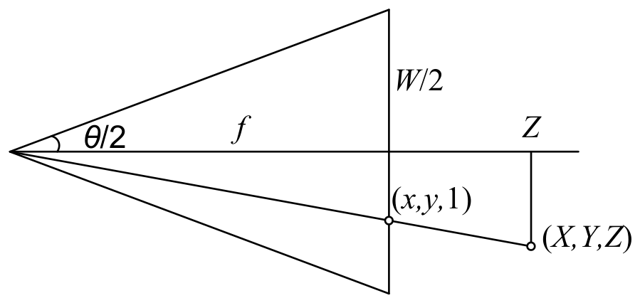
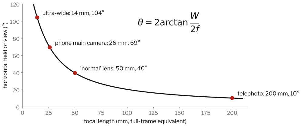
Szeliski (2022), Fig. 2.10 From the triangle: tan ( θ /2 ) = ( W /2 ) / f θ = 2 arctan ( W / ( 2 f ) ) W
The chart is for a sensor 36 mm wide (called "full frame"). Phone cameras have tiny sensors and tiny focal lengths (about 4 to 7 mm). So phone makers write the equivalent focal length: the focal length that gives the same view on a 36 mm sensor. That is why a phone's "26 mm" lens is really about 4 mm.
Simple rule: long focal length = narrow view = things look bigger and flatter. Short focal length (wide angle) = more fits in the picture, but strong perspective.
Part 2: Lenses
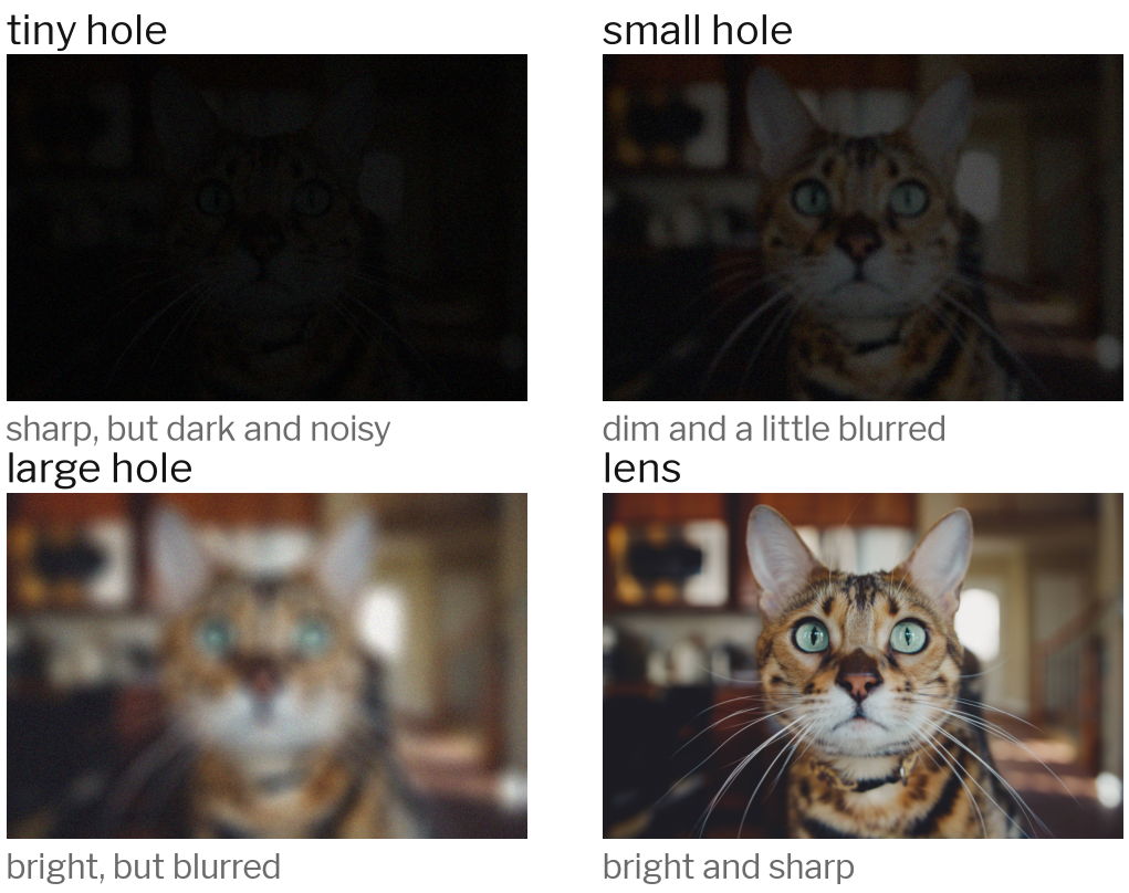
A pinhole makes a perfect picture, but lets in almost no light.
Why we need lenses
Cat photo: Caleb Woods, CC0, via Wikimedia Commons Go from left to right, top to bottom.
A tiny hole gives a sharp picture, because each point sends light through only one spot. But almost no light gets in. The picture is dark, and the camera's noise is very visible. (If the hole is extremely small, the picture becomes blurry again because of diffraction.)
A large hole lets in a lot of light. But each point now spreads into a small disc on the sensor: blur.
A lens gives the best of both. It collects light through a big opening, and bends all the light from one point back to one point.
These pictures are a simulation: blur with a disc that grows with the hole size, brightness that grows with the hole area, and the same noise for all. The exact numbers are only an example.
Focus and depth of field
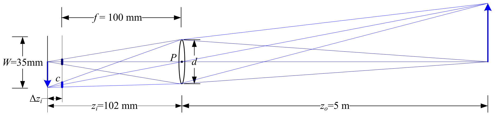
Szeliski (2022), Fig. 2.19 Thin lens rule: z o 1 + z i 1 = f 1
Only one distance z o c depth of field .
Explain with the drawing:
An object at distance z o z i f = 100 z o = 5 z i = 102
Points closer or further away are sharp in front of or behind the sensor. On the sensor they become a small disc, the blur circle c
If c depth of field .
The opening of the lens is the aperture d f-number N = f / d
Examples students know: portrait mode on phones blurs the background (small depth of field). Phones fake this: they estimate distance with a vision method, and then blur the far parts. Landscape photos are sharp everywhere (small opening).
Link to vision: the amount of blur tells us something about distance. This is called depth from defocus .
Lenses are not perfect
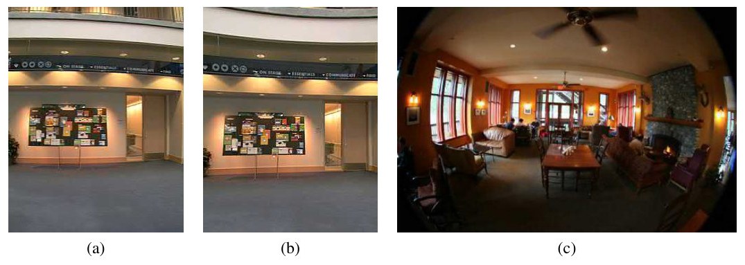
Szeliski (2022), Fig. 2.13
Radial distortion : straight lines bend outwards (barrel) or inwards (pincushion). We describe it with r ′ = r ( 1 + k 1 r 2 + k 2 r 4 ) Vignetting : the corners are darker. Chromatic aberration : colours focus at slightly different places.
Part 3: Light and colour
How bright, and what colour?
Surfaces reflect light in different ways
Szeliski (2022), Fig. 2.16
Matte (diffuse) : light spreads evenly. Brightness depends on the angle between the light and the surface.Shiny (specular) : a bright spot that moves when you move.Shadows and folds : little light gets in.
One pixel number mixes light , material , shape and viewpoint .
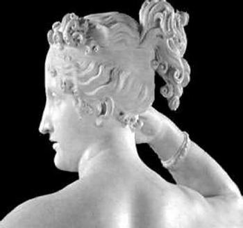
Use the statue to point at each effect:
Cheek and neck: smooth matte shading . A surface facing the light is bright. A surface turned away is darker. The rule (Lambert's law): brightness ∝ cos θ θ
Small bright spots on the hair and shoulder: shiny highlights . They move when you move your head. Matte shading does not.
The folds: darker, because little light can get in.
The last line is the key message. It connects to the illusion in lecture 1. One number per pixel depends on four unknown things. So finding the material or the shape from brightness alone is very hard. Methods that try ("shape from shading") add rules like "the surface is matte" and "there is only one light".
Colour is three numbers
Szeliski (2022), Fig. 2.28
Light has many wavelengths (colours of the rainbow), from about 400 to 700 nm.
Our eyes have three types of colour cells , so we see only three numbers' worth.
Cameras copy this with three filters: R, G, B . Screens add light (left). Printers remove light with ink (right).
The big idea: colour is not only a property of light. It is what three sensors report. Two different lights that give the same three numbers look exactly the same to us. A camera's filters are a little different from our eyes, so sometimes a camera sees two colours as different (or the same) when we don't. This is one reason why a shirt can look different in a photo.
Fun facts: many birds have four types of colour cells. Some factory cameras ("hyperspectral" cameras) measure dozens of colour bands. This connects to the mango task in lecture 1: ripeness can show in colours we cannot see.
Inside the camera
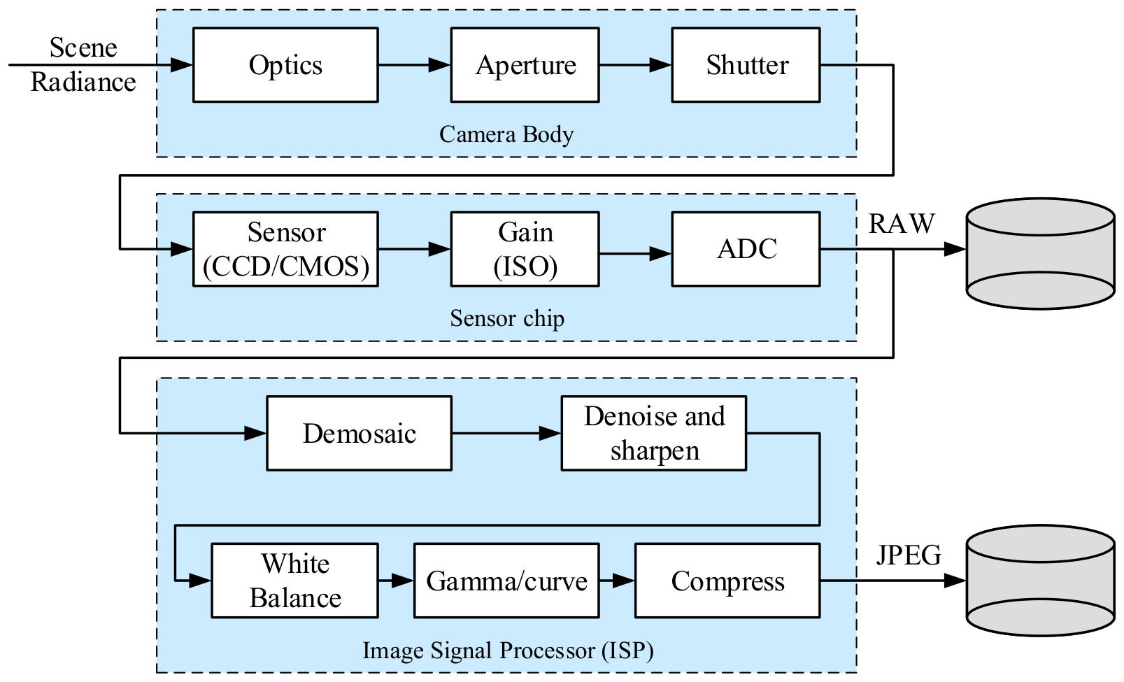
Szeliski (2022), Fig. 2.23 Follow the arrows on the slide:
Lens, aperture, shutter : how much light comes in, and for how long.Sensor (almost always CMOS today): each pixel counts light particles (photons) and turns them into electric charge. Gain (ISO) makes the signal stronger, but also the noise. The converter (ADC) turns the voltage into a number, usually with 10 to 14 bits. This is the RAW file.The image processor inside the camera: demosaicing (next slides), noise removal, sharpening, white balance (making white things look white under yellow indoor light), a brightness curve (gamma), and JPEG compression .
What this means for vision: a JPEG photo is heavily processed . The numbers are not simply proportional to the light. Phones also add strong "AI" processing. For measuring tasks, engineers often use RAW pictures.
Noise sources to name: photon noise (light arrives in random packets, so dark pictures are noisier), electronic noise , and rounding noise (numbers are rounded to whole numbers).
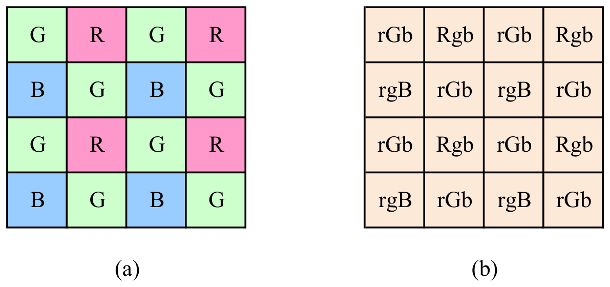
One colour per pixel: the Bayer filter
Szeliski (2022), Fig. 2.31
Each pixel measures only one colour. There are two greens for each red and blue.
The two missing colours (lower case, right) are guessed from the neighbours.
Each pixel of the sensor sits under one colour filter. The usual pattern (the Bayer pattern) has two greens for each red and each blue. Why? Our eyes are most sensitive to green, and green carries most of the detail.
So a "12 megapixel colour camera" measures only 12 million single numbers. Two-thirds of the colour values are guessed from the neighbours. In the right drawing, capital letters are measured and small letters are guessed.
Rebuilding colour: demosaicing
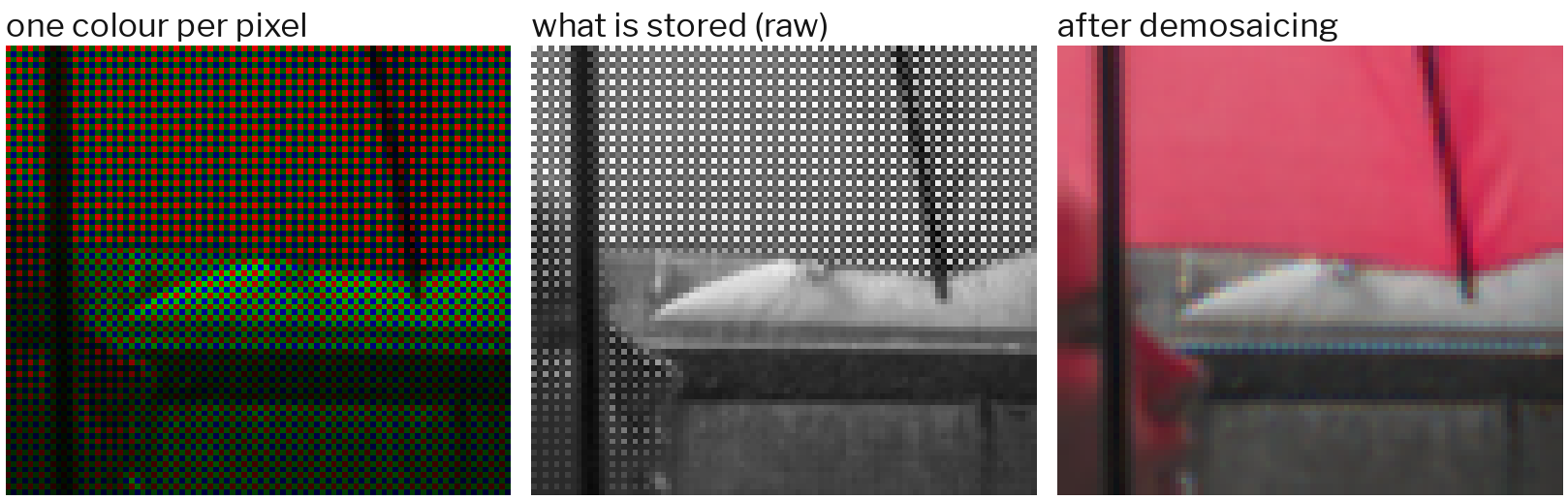
Umbrella photo: keith ellwood, CC BY 2.0, via Wikimedia Commons Filling in the missing colours is called demosaicing . This figure is a real photo (the rim of a red umbrella). We turned it into a Bayer pattern in code, and then rebuilt it.
Left: each pixel coloured by its one filter.
Middle: what the RAW file really stores. One number per pixel. The checkerboard texture is the filter pattern.
Right: the rebuilt colour picture. Look closely at the sharp edges: there are thin coloured lines. These are demosaicing mistakes. They often appear on fine details like text and fabric.
Gamma: the numbers are not the light
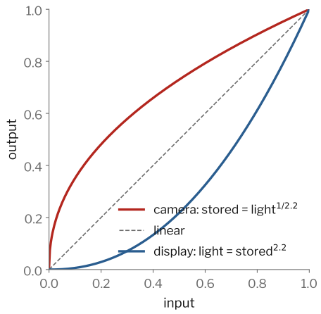
Stored number ≈ light1/2.2
Cameras do not store a number proportional to the light. They use a gamma curve: roughly light to the power 1/2.2. (The exact standard is called sRGB.) The screen does the opposite, so in the end the picture looks right.
Why? With 8 bits there are only 256 numbers. Our eyes notice small changes in dark areas, but not in bright areas. Gamma uses more of the 256 numbers for dark tones. So dark areas do not show visible steps.
A trap for vision: averaging two pixels, blurring, resizing or mixing pictures on gamma numbers is not the same as mixing the real light. Exact methods first convert back to linear numbers. Most libraries ignore this, and usually it does not matter much. But it explains some dark lines around edges in resized pictures.
Part 4: From signal to numbers
Say: "The sensor measures each pixel. Now: how many pixels, how many levels, and how do we store colour?"
Sampling: how many pixels?
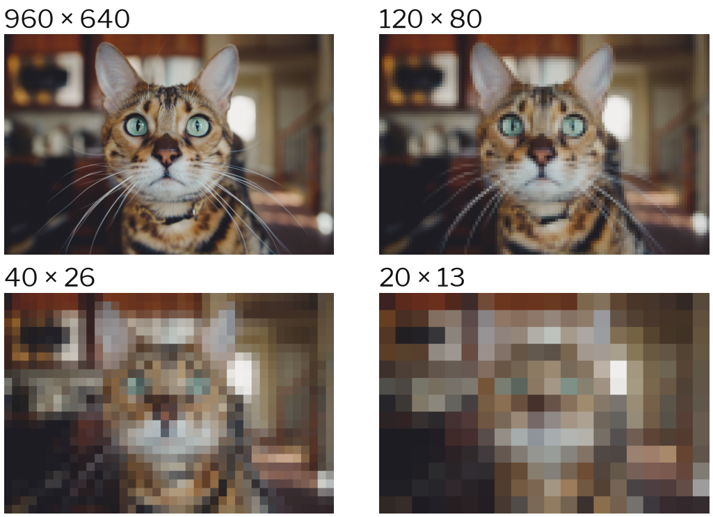
Cat photo: Caleb Woods, CC0, via Wikimedia Commons Sampling means choosing where to measure: one number per pixel, on a grid. Fewer pixels means less detail. At 40 × 26 you can still see it is a cat. At 20 × 13 you can barely tell.
Two points for later lectures:
Many recognition tasks work well with few pixels. Older face detectors used windows of 24 × 24 pixels. Many classification networks use 224 × 224 pixels. Fewer pixels means faster processing.
If we sample too coarsely, we do not only lose detail. We can also create false patterns (aliasing): strange stripes on shirts on TV, or car wheels that seem to turn backwards in videos. That is lecture 3.
Quantization: how many levels?
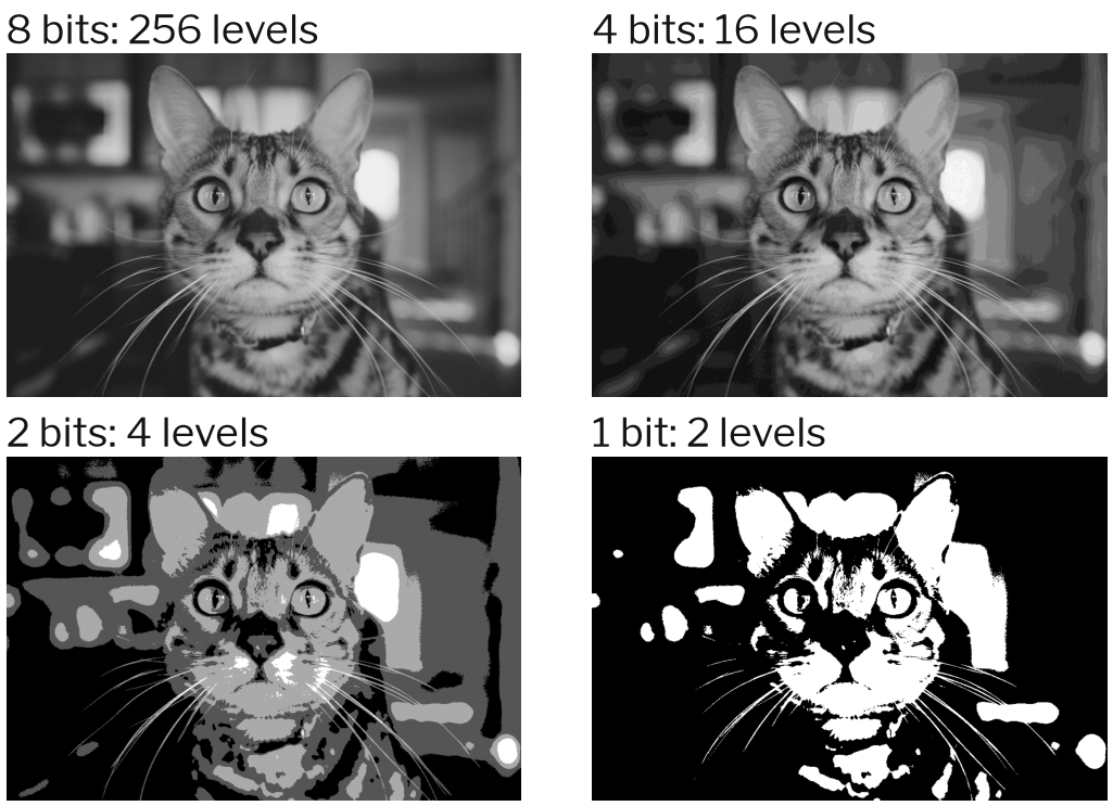
Cat photo: Caleb Woods, CC0, via Wikimedia Commons Quantization means choosing which numbers are allowed. With 8 bits (256 levels), we cannot see the steps. With 4 bits (16 levels), smooth areas (like the blurry background) start to show false edges . With 1 bit, only black and white are left.
Numbers to know:
Most pictures: 8 bits per colour, numbers from 0 to 255 (uint8).
Camera RAW: 10 to 14 bits. Medical and science pictures: often 12 to 16 bits.
HDR and many deep learning programs: decimal numbers (float).
Tip: change to float32 before doing maths. The uint8 mistake (200 + 100 = 44) is very common.
Colour spaces
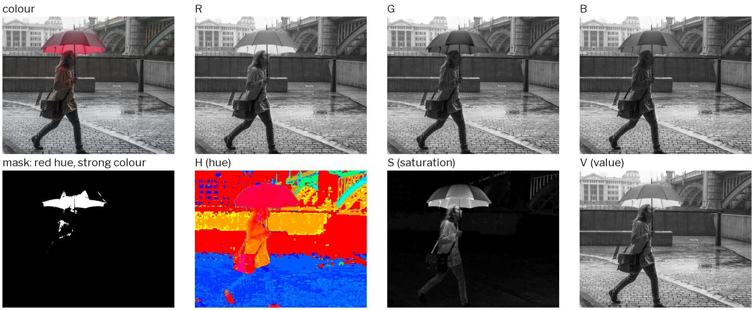
Umbrella photo: keith ellwood, CC BY 2.0, via Wikimedia Commons HSV separates hue (which colour) from saturation (how strong) and value (how bright).
Look at the R, G and B channels. The umbrella is bright in R and dark in G and B. But some light grey areas (the sky, the wet ground) are also bright in R. With RGB it is hard to say "red" without also catching bright grey.
In HSV, the hue says which colour, and does not change much with brightness. So one hue rule plus one saturation rule (strong colour only) gives the mask at the bottom left: almost only the umbrella. A few small red things are also caught.
Look at the hue picture: in grey areas the hue looks like random noise. Grey has no clear colour, so its hue is unstable. That is why we also need the saturation rule.
Other colour spaces to mention:
Grey : 0.299 R + 0.587 G + 0.114 B YCbCr : brightness plus two colour channels. JPEG and video use it.L*a*b* : made so that equal distances look equally different to people. Used to measure colour.
Live: finding a colour
import cv2
img = cv2.imread("red-umbrella.jpg")        # BGR, uint8
hsv = cv2.cvtColor(img, cv2.COLOR_BGR2HSV)  # H is 0..179 (!)
h, s, v = cv2.split(hsv)

red = ((h <= 8) | (h >= 168)) & (s > 120) & (v > 50)
print(red.mean())                           # 0.028 -> about 3% of the photo

cv2.imwrite("mask.png", red.astype("uint8") * 255)
Run this live if you can. The photo is at lecture.williem.app/figures/photos/red-umbrella.jpg. Save it as red-umbrella.jpg, and the output will match the slide.
Points to make while it runs:
In OpenCV, hue goes from 0 to 179 , not 0 to 359, so it fits in one byte. Red is at both ends: near 0 and near 179. That is why we need two conditions joined with | (or).
How did we choose the numbers? By testing. Print h[y, x] at a few pixels on the umbrella. Here most umbrella pixels have hue 173 to 176.
The result is a mask : True or False for each pixel. Its mean is the fraction of pixels that are True. This is the simplest kind of segmentation. Lecture 10 builds on it.
Compression changes the numbers
Szeliski (2022), Fig. 2.34 JPEG throws away detail we probably will not notice: blocks , ringing near edges, smeared colour .
JPEG cuts the picture into blocks of 8 × 8 pixels. It keeps the rough content of each block and throws away the fine detail. It also stores colour at a lower resolution than brightness, because our eyes care less about colour detail. Lecture 3 explains "fine detail" with the idea of frequency.
For vision: a model trained on clean pictures can fail on heavily compressed pictures (CCTV, WhatsApp). Training data should have the same compression as the real system. For measuring, or for training data you control, save as PNG (no loss).
Summary
Geometry : x = f X / Z P = K [ R ∣ t ] Lenses : they collect light, but bring focus, depth of field and distortion.Light and colour : one pixel mixes light, material, shape and viewpoint. Colour is three filtered numbers.Inside the camera : Bayer filter → demosaicing → white balance → gamma → JPEG. The file is not raw light.Numbers : sampling (how many pixels), quantization (how many levels), colour space (how to describe colour).
Ask students to name one thing from each line that could go wrong in a real system. Examples: distortion bends lines; shiny spots look like white objects; demosaicing makes false colours on text; JPEG blocks look like edges; quantization hides dark details.
Exit ticket
A point is 10 m away and appears 50 pixels from the centre of the picture. Where would it appear if it were 20 m away, in the same direction?
Why do phone cameras have two green pixels for every red and blue one?
Name two reasons why a pixel number is not a direct measure of the light from that point.
Next lecture: pictures as signals. Histograms, frequency, and why fine stripes can turn into big false patterns.